OpenSpace 5: Difference between revisions
| Line 160: | Line 160: | ||
Eventually, which methods for decelerating the Space Catapult’s rod would be the best? As we see each one of them have got their advantages and disadvantages. We can state that we should choose one of them according to spaceflight’s profile and goal. Particularly, if we decide to send the spacecraft into the deep space mission where especially high speed is necessary then in this case ''longer/more massive'' rod would be needed rotating at very high speed. Under such circumstance much energy will be needed for accelerating/decelerating the rod. We should also take into consideration the fact how frequently the Space Catapult will operate, in other words how mane payloads it will have to send into space per some certain amount of time, week/month and etc. If time interval between two following missions is relatively high then we should choose the method that will consume less energy and more time for decelerating the rod. On the contrary, if the Space Catapult has to send payloads very often then we should choose the method that will consume more energy and enable the rod to decelerate faster. In other words, we should find ''golden mean'' between consuming time and energy. We should also take into account how much energy supply will be produced at the Space Elevator’s counterweight (see ''Energy source placed on the Space Elevator’s counterweight'') and what part of this energy can we spend for accelerating/decelerating the rod. | Eventually, which methods for decelerating the Space Catapult’s rod would be the best? As we see each one of them have got their advantages and disadvantages. We can state that we should choose one of them according to spaceflight’s profile and goal. Particularly, if we decide to send the spacecraft into the deep space mission where especially high speed is necessary then in this case ''longer/more massive'' rod would be needed rotating at very high speed. Under such circumstance much energy will be needed for accelerating/decelerating the rod. We should also take into consideration the fact how frequently the Space Catapult will operate, in other words how mane payloads it will have to send into space per some certain amount of time, week/month and etc. If time interval between two following missions is relatively high then we should choose the method that will consume less energy and more time for decelerating the rod. On the contrary, if the Space Catapult has to send payloads very often then we should choose the method that will consume more energy and enable the rod to decelerate faster. In other words, we should find ''golden mean'' between consuming time and energy. We should also take into account how much energy supply will be produced at the Space Elevator’s counterweight (see ''Energy source placed on the Space Elevator’s counterweight'') and what part of this energy can we spend for accelerating/decelerating the rod. | ||
The rod’s rotations can be decelerated much faster than accelerated; the reason of it is that when accelerating the rod has got some sophisticated device as payload and generally unmanned spacecrafts are capable to high g-loads, but still for them some restrictions exist. After the payload is released at needed direction and speed, the rod can decelerate much faster because the rod itself is quite simple device without any complex and sophisticated details. | |||
We can actually use several methods, such as the third one and then the first/fifth ones. This would be justified because of following reason: as we have already said when decelerating with the third/forth method the problem of weakness of the Earth’s magnetic field would occur, therefore much time would be necessary for described method(s) to perform and give us result. However, we should note that in the beginning when the rod rotates very quickly this method would still operate strong enough. This derives from Faraday's law of induction stating that “the electromotive force generated is proportional ''to the rate of change of the magnetic flux''”. Therefore, in the beginning when the rod is rotating very quickly we can use the third/forth method(s) and when the rod significantly brakes we can apply to the first/fifth ones-they do not depend on Earth magnetic field. In other words, such approach would greatly help us in finding the golden mean between spending energy and time necessary for decelerating the rod. | |||
And finally: after releasing the payload the Space Catapult’s rod can actually give us energy. More precisely, the electro motor itself can serve as electric generator also since we know that the same machine can operate as electric motor if it is fed with electricity and as generator for electricity if its rotor is rotated by other machines. Therefore after releasing the payload when the electro motor’s rotor is rotating very quickly it can give us energy, in result of which the rod will lose its kinetic energy and speed, as for generated energy it can be sent downwards to the Earth for our terrestrial needs (see the next section in this paper) or stored onboard the Space Elevator’s counterweight. This approach has got one substantial advantage: it does not imply additional mass (wrapped wire) that will cause problems because rotating heavier rod would consume more energy. | |||
Revision as of 10:39, 21 September 2013
| Title: Place Title Here | ||
|
[Cover Img] |
About:
|
Tags:
|
Space Catapult
Author: Mr. Giorgi Lobzhanidze
Address: Tbilisi, Republic of Georgia, Europe
Email: mailto:giorgi9@gmail.com
INTRODUCTION
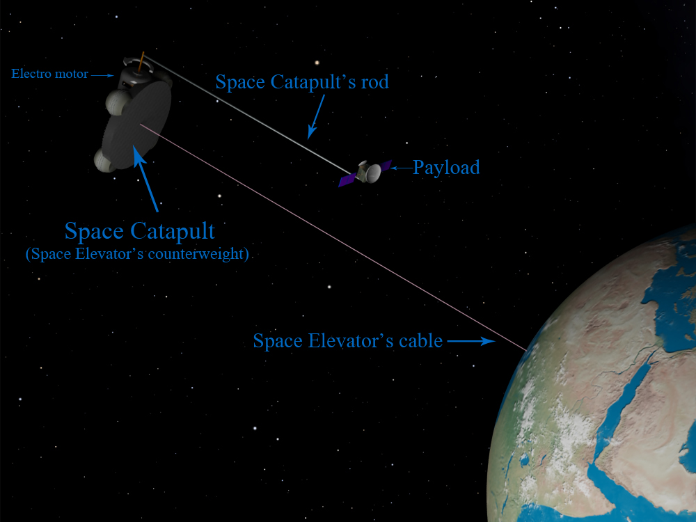
The new method for sending the spacecrafts in deep space is presented here. The paper describes the long rod rotated by electro motor placed at the Space Elevator’s counterweight and at Lagrangian points. This simple structure will enable the rod to gain high velocity and carry the payload with it. After reaching the desired speed the rod will release the payload that will fly in space along the imaginary circle’s tangent. This structure we called Space Catapult and it should work with the assist of Space Elevator. This latter should be used for carrying the payload from the Earth to Space Catapult’s rod.
For exploring the outer space the humankind generally uses the rocket engines, mostly chemical-propelled ones. They enable us the explore near-Earth celestial bodies and other planets in the solar system. They even enabled us to send several deep space missions beyond the solar system such as Pioneer-10, Pioneer-11, Voyager-1, Voyager-2, however by means of this technology the flight lasts undesirably long and it seems to be impossible to reach remote celestial bodies in space such as stars, so new technologies are necessary for this purpose. However new technologies do not necessary imply new kind of rocket engines, such as Ion Drives because they are capable for gaining several ten times higher speeds only, but for remote celestial bodies even they are not suitable. Besides, they need a huge amount of energy to be stored onboard the spacecraft and this will make additional problems. So, high speed should be achieved with absolutely different approach. How this can be done?
High speed can be easily achieved by means of fast-rotating rod around the electric motor. The motor’s rotational speed can be very high; the rod also can be quite long, hence the rod’s end’s linear speed can be extremely high, absolutely unachievable for any other technologies nowadays. The payload should be fastened at the rod’s end where the linear speed generally reaches maximal value. After reaching the necessary speed the rod will release the payload that will fly along the tangent from the current position. Thus the electric energy can be turned into payload’s speed and its velocity could be as high as we wish (except the speed of light of course). In principle the Space Catapult (thus we call this structure) would be the simplest, the most convenient and direct way for converting the energy/electricity into speed and conveying it to payload.
As we see the Space Catapult is quite uncomplicated structure, however if we wish to gain high speeds we should deploy it in space, not on the Earth. Indeed, our planet is surrounded with dense atmosphere that impedes any quick motion, so if we rotate the rod quickly the atmospheric drag and generated heat would burn it very soon, therefore the Space Catapult should be built and deployed in space only, and as we suppose-at the Space Elevator’s counterweight. In other words, the Space Elevator’s counterweight will operate as Space Catapult. See image below:
 Generally, what is the Space Elevator 1 2? According to modern concepts it will be the tall vertical structure built on equator and will have height of several ten thousand kilometers with its thin cable fastened to the base station on the Earth and with counterweight placed higher geostationary orbit. Because of balance between centrifugal force and gravity this structure will be stretched and the cabin will move along its cable carrying the goods into high orbit. After delivering the payload, the cabin will descend and carry the next one.
In Space Elevator’s concepts several solutions have been proposed to act as a counterweight:
1. Heavy, captured asteroid
2. Space dock, space station or spaceport positioned past geostationary orbit
3. Extension of the cable itself far beyond geostationary orbit.
The third idea has gained more support in recent years due to the relative simplicity of the task and the fact that a payload that went to the end of the counterweight-cable would acquire considerable velocity relative to the Earth, allowing it to be launched into interplanetary space. However this idea cannot be completely shared by us due to following reason:
It is well-known that the values of both Orbital and Escape Velocities decreases with increasing the altitude while the tangential velocity of Space Elevator’s cable increases. We can see the differences between them from the chart presented below:
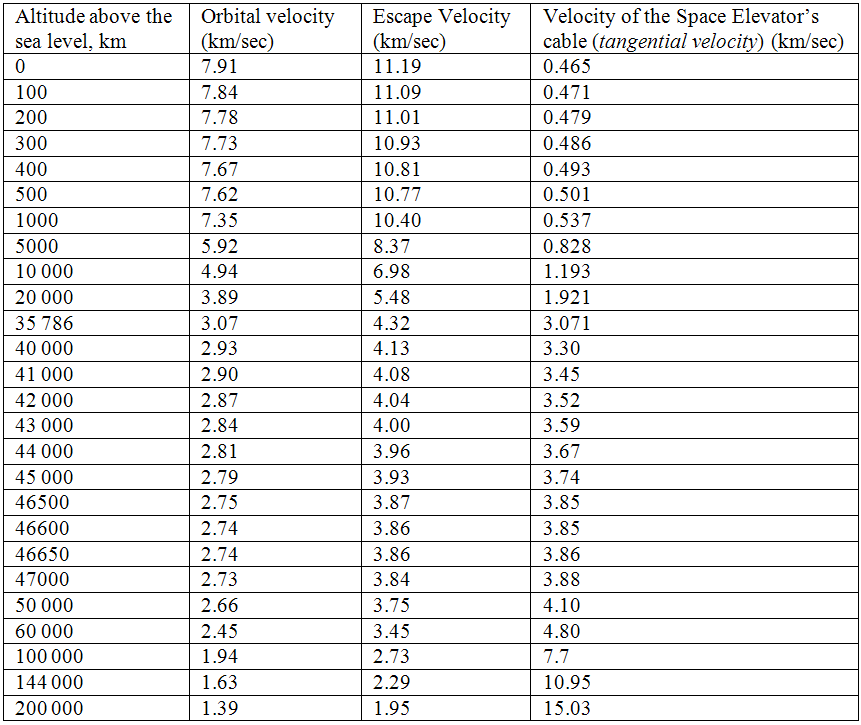
As we see from this chart the tangential velocity of the Space Elevator even at its end (144 000 or 200 000 km altitude) is not very high to decrease the necessary time for covering the distance from the Earth to remote celestial bodies significantly. To achieve this, even the longer Space Elevator would be needed (its tangential velocity is directly proportional to its length) and this circumstance would complicate the technical task for building such Space Elevator. Because of this, there is no necessity to extend the cable itself far beyond geostationary orbit as proposed in the third variant. In any case, we have already seen that by means of Space Catapult it is possible to gain such huge velocities that are absolutely unachievable with other technologies, for example with Space Elevator. Therefore, using the counterweight and placing the Space Catapult there definitely has got some technical sense.
However, we think that the question where the Space Catapult should be placed needs further discussion. Theoretically, the Space Catapult with its payload and nuclear reactor/solar panel needed for rotating the rod may be mounted not only at the counterweight, but on the Space Elevator’s cabin also that can carry all these goods to space in a usual way, as it should do it according to Space Elevator’s modern concepts. This option is quite possible, however for realizing this we need to know the mass of the payload, nuclear reactor/solar panels’ mass plus Space Catapult’s mass from one hand and Space Elevator’s lifting capacity (this must be more) from other hand, but these data are not available nowadays, therefore we think that the Space Catapult should be still mounted at the Space Elevator’s counterweight where it will be possible to send the payloads into deep space in continuous mode at high velocities.
As we saw the Space Catapult is capable to gain very high velocities; however there is being developed other technologies and they in future will enable the spacecraft to fly at high speeds in space. These are Ion Drive systems, more precisely the most perspective one-Variable Specific Impulse Magnetoplasma Rocket (VASIMR) which still under development can be used in future for deep space missions. Can these engines and Space Catapult be the rivals in space? Since none of them have been built and used in space yet we cannot give a persuasive answer to this question; however still it is possible to underline Space Catapult’s one significant advantage: if the future spacecraft uses the VASIMR (or any other kind of Ion Drive) engine it will definitely need to be equipped with nuclear reactor, otherwise the spacecraft will not be able to gain high speeds, also it will need to carry fuel tanks for this purpose. As for the Space Catapult, it can give much higher speed to spacecraft, besides it will have stationery power plant (see Energy source placed on the Space Elevator’s counterweight) at the Space Elevator’s counterweight, so the payload will not have to carry the nuclear reactor onboard and this circumstance will lighten the work for deep space spacecraft. Besides, we should not forget that unlike the spacecrafts equipped with ion drive engines the Space Catapult will need no fuel for gaining high velocities.
Briefly, Space Catapult’s advantages over any kind of propulsion systems are:
1. Ability to gain any speed that is absolutely unachievable by means of other kinds of engines.
2. No need by spacecraft to carry energy source that would make it too heavy and impracticable.
The Space Catapult needs long rod
When building the Space Catapult at Space Elevator’s counterweight we should install quite long rod there, the shorter the rod is, the easier would be installing it, however we should note that rod cannot be extremely short, let’s say 1 km length or so due to following reason:
When we are going to send some payload into space, we need not only high velocity, but one certain direction also. The little inaccuracy in direction, inclination in several arcminutes is actually acceptable since the spacecraft would easily balance it with its engines; however great inclination from the initial direction would send the spacecraft into the completely different direction and in such case the whole mission will fail.
If two Space Catapult’s rods have the length of let’s say 1 kilometer and 10 kilometers, then for giving to payload some certain linear speed (for instance 100 km/sec) these rods should rotate at different angular velocity. It is easy to ascertain that the shorter rod should rotate 10 times faster to gain the same linear speed than the rod with more length. But the faster the rod rotates, the more difficult will be to “catch” the needed moment for releasing the payload from the rod for sending it towards some certain direction. If the rod is too short, then it has to rotate very quickly for gaining some certain linear speed and therefore it will be extremely difficult catching the needed moment for releasing the payload. Hence, too short rod can make problem for sending the payload to some certain direction in space especially at high velocities. So, based on payload’s needed velocity we should find rod’s desired, minimal length that will enable us to send the payload in space to necessary direction without fear that it may yaw from the course.
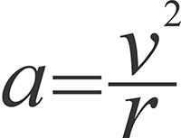
However, rod’s length will be crucial for payload’s abilities for withstanding the acceleration also. As an example, we can try to calculate its value which the payload will have to withstand during rod’s rotation. The acceleration of the body rotating at the circle with some constant velocity is calculated by the following formula:
Where a is acceleration in m/sec2, v is payload’s linear velocity on the circle in m/sec and r is radius of the circle in meters, in our case it is equal to rod’s length. Let’s assume that the rod is 100 km length and the electromotor rotates it so that payload’s speed is equal to 50 km/sec, in this case acceleration will be equal to 25 000 m/sec2, which is about 2550 g. The modern technologies enable to design and manufacture the spacecraft’s subsystems (avionic and etc.) capable to withstand such acceleration. This circumstance somehow restricts the speeds that we can achieve, in any case their values actually depends on spacecrafts’ abilities for withstanding g-loads. But what can we do if much higher speeds are needed? The answer directly derives from that formula: the radius should be more; by the way note that this is additional reason why the longer rod is more useful. If we are able to make the extra long rod, then this will enable us to gain much higher velocities.
What material should be used for manufacturing the rod? It is obvious that if very high speeds are needed the rod should be long and even in this case the acceleration at its end will be quite high, therefore sufficiently strong and light materials are needed for this purpose and making them is as similar challenge as in case of Space Elevator where the same requirements arises for the cable’s material. The lightness is needed because in case of heavy rod a lot of energy will be needed to rotate it; the strength is needed because in case of lack this property the rod will be destroyed due to great acceleration.
The mechanism for holding and releasing the payload
How the payload can be held by Space Catapult’s rod during rotation and how it can be released from the rod? We think that using electromagnet plus mechanical holding devices would be a good solution. More precisely, after the payload is attached to the rod it must be held by means of both methods until the rod accelerates and reaches necessary velocity (it may take even several days), but with approaching the desired speed the mechanical device should release the payload however the electromagnet(s) should still hold it. The explanation of such approach is following: generally the mechanical devices are much slower/sluggish in performance than electronic ones. We have already said that when releasing the payload the extreme accuracy is needed and mechanical devices cannot guarantee the exact time of releasing the payload unlike electronic ones. That is, it’s unlikely that mechanical devices can release the payload at some certain moment when needed while in case of electromagnet it would be enough to cease electric current there, it would lead to immediate vanishing of the magnetic field and sending the payload along the tangent from the point where the payload would be at the current moment.
We think that the fastest control system would enable to release the payload to certain direction. This system (extremely fast-operating computer plus measuring equipments) should know the current position of the rod’s end, the current speed, the needed direction and be capable for computing the necessary moment for giving the order for diminishing the voltage for electromagnets and hence releasing the payload to desired direction and velocity.
Rod’s plane of rotation towards the Earth
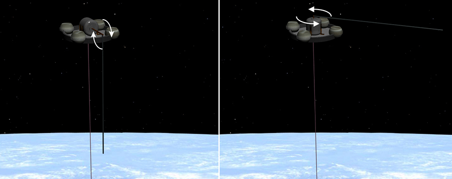
The Space Catapult’s rod when rotating makes the circular plane/flatness in space and this plane may be horizontal/parallel to Earth surface, that is making the right angle to Space Elevator’s cable or it may be placed along the cable; see the both possible situations here:
Both approaches have got their advantages/disadvantages and here we will discuss this question, first of all from the point of view of safety.
For gaining extremely high velocities quite long rod would be needed, maybe with the length of several thousand kilometers or even more. If such rod is placed along the Space Elevator’s cable then the rod during rotation will cross many orbits from the Medium Earth Orbit to High ones. When rotating, the rod may actually hit any satellite and/or space debris object and such collision can lead to rod’s complete destruction; therefore we should choose such plane which would be much more free from any artificial objects; hence if the rod rotates horizontally/parallel to Earth’s surface at high enough altitude where the satellites’ population is relatively low then this measurement would justify itself because under such circumstance the rod will not cross satellites’ orbits (rod’s plane of rotation will simply coincide to one orbit’s path). However, we should also note that this altitude actually depends on the Space Elevator’s proposed length. Indeed, the Space Catapult’s rod should be mounted at the Space Elevator’s counterweight; this counterweight from its side should be placed at the end of the Space Elevator at such altitude where the satellites’ population is as low as possible. This means that Space Elevator’s proposed height should be agreed with mounting Space Catapult on its counterweight. According to various databases the number of man-made objects at high orbits, more precisely beyond geostationary orbit is much less than on the lower orbits 3 4 5 6, therefore the Space Catapult with its rod should be located at the altitude of 50 000-60 000 km above the sea level. At such altitude the space is almost free and nothing will impede rod’s rapid rotation. Besides, the satellites at high orbits are orbiting around the Earth slower than on the lower orbits (as known any satellite orbits around its primary body slower in apogee than in perigee), therefore if some tracking system is mounted at Space Elevator’s counterweight then it will enable the Space Catapult to avoid undesired collision with satellites during Space Catapult’s performance. In other words, the Space Catapult should operate only when the there are no satellites near its vicinities.
Now we will try to discuss this question from other side.
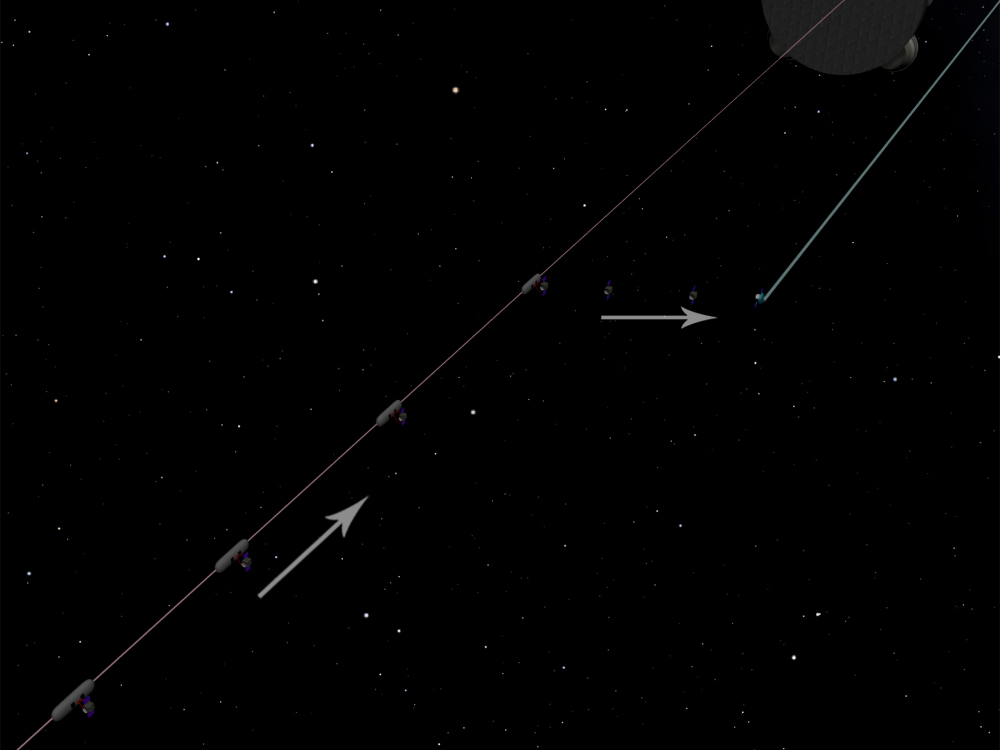
How the payload can be transferred from the Space Elevator’s cabin to the Space Catapult’s rod? One way is following: cabin reaches the counterweight where the payload will be released, then payload will be mechanically conveyed to rod, continues its way on the rod (like the train rides on the rails) and after reaching rod’s end it stops, the rod begins rotating and after gaining necessary linear speed it releases the payload to needed direction. This method is generally realizable; however it seems to be too complicated and unpromising compare to the second one: the Space Catapult’s rod is stopped in space so that it to be directed downwards to the Earth and be parallel to Space Elevator’s cable. The Space Elevator’s cabin moving along the cable with payload stops at the cable near the end of the Space Catapult’s rod and releases the payload that will fly to the rod, attaches itself to the rod’s end (here the electromagnets would be useful), the rod begins rotating and after gaining needed linear speed will release the payload to necessary direction.
This second way seems to be more promising because the first one is much more complicated as we have already said: first of all there would be needed some mechanical devices for transferring the payload from the Space Elevator’s cabin to counterweight, the counterweight should have the hole for the payload to move through it from below (we should not forget that the Space Catapult should be mounted at the counterweight, not beneath it), besides the rod should be made so that it to have some conveying surface (rails for instance) the payload to move on it. As we see it would be much more convenient if it is possible to convey the payload from the cabin to the rod directly and this would be feasible under the second method which is depicted below:
One more aspect regarding Space Catapult’s position. This structure, its rod, its electro motor and etc should be mounted at Space Elevator’s counterweight so that the rod to be placed westwards from the cable. The reason of it is following: when the Space Elevator’s cabin stops and releases the payload (which should fly to Space Catapult’s rod) the current speed of which will/should be more than the value of the Orbital/Escape Velocity at the current altitude. After releasing the payload will fly westwards and upwards because its orbit will be ellipse, under ellipse the payload will fly higher to apogee and at the speed less than Space Elevator’s current speed at the given altitude, in other words the released payload will “lag behind” the Space Elevator’s cable; therefore payloads’ stopping points at the cable and Space Catapult’s rod’s length should be calculated and chosen so that the payload to fly directly towards rod’s end. This process would be feasible in both cases-if the rod’s plane of rotation is parallel to Earth’s surface and if it is placed along the cable-but still this would be easier for the payload to achieve the rod’s end if the rod is placed along the cable because at least the distance that the payload should cover in space will be less.
The length of the Space Catapult’s rod placed at the Space Elevator’s counterweight might vary since for various spaceflight purposes different initial speed will be needed and relatively low speed could be achieved by means of shorter rod. Because of this reason it might be necessary to change Space Catapult’s rod’s length, therefore it would be useful if the rod consists of two parts where the first part would be perpetually attached to electro motor and the second one will be attached to the first part if necessary. For this operation Space Catapult’s rod should be placed along the cable since the relative nearness would make this operation quite easy and it could be accomplished by the crew directly from the Space Elevator’s cabin stopped at the needed altitude.
For deciding the question how the Space Catapult’s rod should be placed towards the Space Elevator’s cable we should take into consideration one substantial circumstance-to which direction do we plan to send the payload in space by means of Space Catapult? This circumstance will influence deciding this problem due to following reason:
In case if Space Catapult’s rod is parallel to Space Elevator’s cable and if rod’s plane of rotation is parallel to Earth equator, then this plane will be orthogonal to Earth’s rotation axis. This axis from its side is tilted to ecliptic plane by 66° 34'. This means that Space Catapult’s rod’s plane of rotation will be tilted to ecliptic plane by 23°26'. Here follows very important consequence: under above-mentioned conditions the rod when rotating will be capable for covering only the part of the celestial sphere from 0° to 23°26' (counted from ecliptic plane northwards and southwards to Ecliptic poles). This is about one fourth of the celestial sphere (23°/90°), this will not make problems if we intend to use the Space Catapult for exploring the solar system’s planets because their orbits’ tilts towards ecliptic plane do not exceed 7° (for planet Mercury, for other planets this tilt is even less); however we will not be able to send the payload for example to the nearest star Alpha Centaurs because this star is located at -42 degree according to ecliptic coordinate system in the celestial sphere.
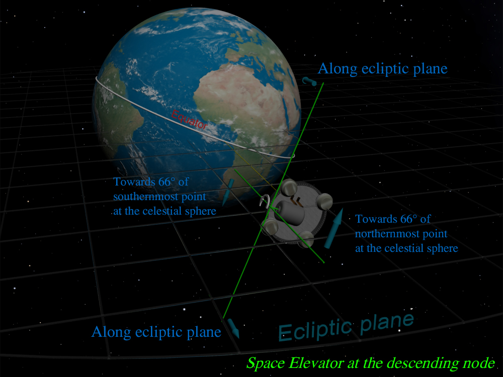
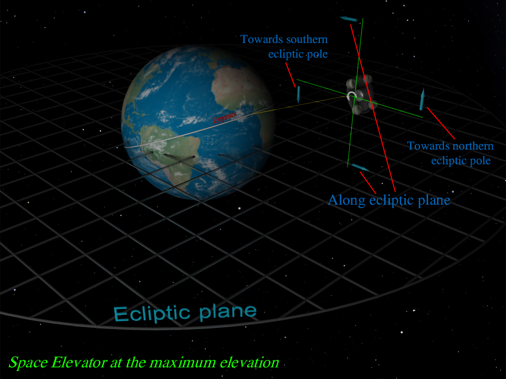
The situation will drastically change if Space Catapult’s rod is parallel to Space Elevator’s cable and if rod’s plane of rotation is orthogonal to Earth’s equator and therefore parallel to Earth’s axis of rotation. We have already discussed this option when we mentioned that the rod should be placed westwards from the cable and explained why it would be useful-for delivering the payload from Space Elevator’s cabin to Space Catapult’s rod. Under such conditions the Space Catapult will be capable to aim to any point on the celestial sphere. Indeed, the Earth with the Space Elevator rotates around its axis and Space Elevator’s counterweight draws an imaginary circle in space. This circle is tilted to ecliptic plane at 23°26' and crosses this plane in two point called ascending and descending nodes. The other points that are 90° away from these nodes we call point(s) of maximum elevation/depression (relative to ecliptic plane). When the Space Elevator is at ascending/descending node its rod and hence the payload can be directed to any point from 0º to 66º on the celestial sphere northwards and southwards from ecliptic plane. This makes about 75 % of celestial sphere. See the image depicting this situation:
But when the space Elevator reaches the points of maximum elevation/depression then its rod during rapid rotation may be directed to any point from southern Ecliptic pole to Northern pole at the celestial sphere because at these points rod’s plane of rotation is orthogonal to ecliptic plane and thus the rotating rod can aim to ecliptic poles as well as other points. See this situation below:
The situation will be similar if the Space Catapult’s rod is orthogonally placed towards cable. Under such approach Space Catapult’s rod’s plane of rotation will be tilted to ecliptic plane by 66° 34' and the Space Catapult will be capable to cover three fourths (66°/90°) of the celestial sphere when the Space Elevator is at the points of maximum elevation/depression and the whole celestial sphere when the Space Elevator is at ascending/descending nodes. For aiming the needed point on the celestial sphere the Earth should occupy the appropriate attitude towards the stars during the revolution around its axis, the same thing should be done under previous case described in the paragraph above.
In conclusion, thinking about rod’s plane of rotation towards the Earth, we should note one important difference between above-mentioned approaches: if Space Catapult’s rod’s plane of rotation is parallel to Space Elevator’s cable, then in case of emergency during Space Catapult’s performance (for example if the Space Catapult’s rod is cut by sudden meteorite bombardment) the rod’s part with the payload may simply crash to the Earth at huge velocity if the rod at this moment is directed to the Earth. This cannot happen if Space Catapult’s rod’s plane of rotation is orthogonal to Space Elevator’s cable because payload’s rotational path will not be directed towards the Earth and hence its flying trajectory will never cross the Earth.
Braking the Space Catapult’s rod
After releasing the payload at necessary speed and direction, the Space Catapult’s rod will have a huge angular velocity that needs to be decreased to zero in order the Space Catapult’s rod to get another payload in motionless position and then to send it to space. What methods can we use to reduce Space Catapult’s rod’s rotation to zero? There are several possible ways:
1. The electromotor designed for accelerating the rod may actually play a role of brakes, more precisely after releasing the payload to space the electromotor should operate/rotate in the opposite direction, hence rod’s rotational speed will be diminished to zero after that electromotor will stop operating. Under such method a bit less energy will be spent for decelerating the rod than in case of accelerating because when decelerating the rod is free from payload.
2. An ordinary mechanical brakes, however due to electro motor’s and rod’s sizes a huge brake(s) would be needed to be installed on the Space Elevator’s counterweight and this circumstance would make additional problems from the engineering point of view. Nevertheless, we should admit that under such method we would not need as much energy as during accelerating; on the contrary, in this process the heat will be emitted as it generally happens during braking.
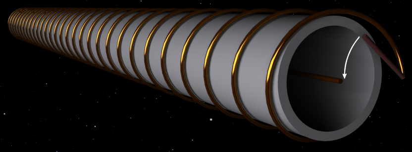
3. For decelerating the rod we can use the well-known phenomenon in physics-electromagnetic induction: when the conductor/ closed circuit moves into the magnetic field the electric current is generated there. In case of Space Catapult we can use this phenomenon in the following manner: the conductor should be wrapped around the whole length of the rod like a helix and there should be possibility that this conductor to be turned into the closed circuit by means of mechanically connecting its ends (see the image below). After releasing the payload at necessary speed and direction this circuit should be closed, then according to electromagnetic induction the electric current will be generated in the conductor and the energy of this electric current will come from rod’s kinetic energy. Therefore, inducted electric current in the enclosed circuit will force this circuit and rod to lose kinetic energy and speed. The part of the generated electric current will be spent in prevailing conductor’s electric resistance:
The advantage of this method is that for decelerating the rod no energy will be required, as for drawback-much time will be required for this purpose because at the altitude of several ten thousand kilometers the Earth’s magnetic field is quite weak and the effect described in the paragraph above will need much time to operate and give necessary result.
4. The above-described third method could be realized in a bit different way: if the conductor wrapped around the rod is a closed circuit and if we conduct the electricity there then the electric current will generate its own magnetic field that will counteract with Earth’s one. More precisely, according to Lenz's law induced current’s magnetic field will be in such a direction as to oppose the motion or change causing it, in other words induced current’s magnetic field will counteract outer magnetic field’s any change and this will cause decelerating rod’s rotation and finally its stopping.
5. The obvious disadvantage of the third and fourth method described above is weakness of the Earth’s magnetic field because of which decelerating the rod may be delayed in time. For solving this problem we can create artificial magnetic field by means of electromagnets. Particularly, one electromagnet should be placed at the Space Elevator’s counterweight, very close to Space Catapult’s rod. The second electromagnet should be placed directly on the Space Catapult’s rod close to first electromagnet (actually, instead of this second electromagnet there could be used the conductor wrapped around the rod as we described above in previous methods). The reason of this nearness is that magnetic field generally weakens directly proportional to distance’s third power and much time will be needed for decelerating Space Catapult’s rod if two electromagnets are far from each other.
This method probably will consume the most amount of energy but at the same time it will be the most effective because it does not depend on outer factors such as Earth’s magnetic field which is quite weak at the altitude of several ten thousand kilometers above the sea level.
Eventually, which methods for decelerating the Space Catapult’s rod would be the best? As we see each one of them have got their advantages and disadvantages. We can state that we should choose one of them according to spaceflight’s profile and goal. Particularly, if we decide to send the spacecraft into the deep space mission where especially high speed is necessary then in this case longer/more massive rod would be needed rotating at very high speed. Under such circumstance much energy will be needed for accelerating/decelerating the rod. We should also take into consideration the fact how frequently the Space Catapult will operate, in other words how mane payloads it will have to send into space per some certain amount of time, week/month and etc. If time interval between two following missions is relatively high then we should choose the method that will consume less energy and more time for decelerating the rod. On the contrary, if the Space Catapult has to send payloads very often then we should choose the method that will consume more energy and enable the rod to decelerate faster. In other words, we should find golden mean between consuming time and energy. We should also take into account how much energy supply will be produced at the Space Elevator’s counterweight (see Energy source placed on the Space Elevator’s counterweight) and what part of this energy can we spend for accelerating/decelerating the rod.
The rod’s rotations can be decelerated much faster than accelerated; the reason of it is that when accelerating the rod has got some sophisticated device as payload and generally unmanned spacecrafts are capable to high g-loads, but still for them some restrictions exist. After the payload is released at needed direction and speed, the rod can decelerate much faster because the rod itself is quite simple device without any complex and sophisticated details.
We can actually use several methods, such as the third one and then the first/fifth ones. This would be justified because of following reason: as we have already said when decelerating with the third/forth method the problem of weakness of the Earth’s magnetic field would occur, therefore much time would be necessary for described method(s) to perform and give us result. However, we should note that in the beginning when the rod rotates very quickly this method would still operate strong enough. This derives from Faraday's law of induction stating that “the electromotive force generated is proportional to the rate of change of the magnetic flux”. Therefore, in the beginning when the rod is rotating very quickly we can use the third/forth method(s) and when the rod significantly brakes we can apply to the first/fifth ones-they do not depend on Earth magnetic field. In other words, such approach would greatly help us in finding the golden mean between spending energy and time necessary for decelerating the rod.
And finally: after releasing the payload the Space Catapult’s rod can actually give us energy. More precisely, the electro motor itself can serve as electric generator also since we know that the same machine can operate as electric motor if it is fed with electricity and as generator for electricity if its rotor is rotated by other machines. Therefore after releasing the payload when the electro motor’s rotor is rotating very quickly it can give us energy, in result of which the rod will lose its kinetic energy and speed, as for generated energy it can be sent downwards to the Earth for our terrestrial needs (see the next section in this paper) or stored onboard the Space Elevator’s counterweight. This approach has got one substantial advantage: it does not imply additional mass (wrapped wire) that will cause problems because rotating heavier rod would consume more energy.
