SER 2 1
| Title: Woven Interconnects | ||
|
About:
|
Tags:
|
|
Woven Interconnects - Open Discussion
Some time back I had a discussion with a textile person on the merits of weaving the interconnects like a cloth rather than using "tape sandwiches". There are some very positive aspects of this and a few drawbacks.
- Pure CNTs can be used in woven interconnects that will not have environmental issues like those expected for adhesives, plastics,...
- Pure CNT interconnects could hand extreme temperatures
- Woven interconnects are not viable for high-speed splicing and difficult to use in repair of the ribbon
- ???
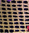
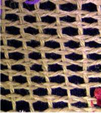
I remember having information (hardcopy) on types of weaves that lock in the cross threads. The simplest is a Leno weave (image). In the Leno weave axial threads are straight and two cross threads will pass on either side of an axial thread then twist once around each other then pass the next axial thread on the same side they started on. This is continued across the set of axial threads and either tied off or brought back on the next pass.
This weave tightens when pulled. It also instills an automatic, consistent spacing. Something like this might do well.
So, to make this work we need to know how slippery the CNTs are and design the number of cross lines around this. The slipperier the CNTs are the more cross threads we need. The good part about this is that it is old technology, experts know what will happen... maybe we should talk with them. It would also be good to see how this deforms under degradation.
We can start looking at the design by considering a ribbon with 10,000 axial threads and interconnects every 1 m in the section we are examining. These are just numbers to make things easy. Lets also look at one pair of interconnect threads in each interconnect.
Assumptions:
- axial fibers are essentially rigid - don't deform under pressure by interconnect threads
- interconnect threads have a set tension and angle to axial threads
- fix the coefficient of friction between the axial and interconnect threads
Interconnect thread angle to axial thread is A (this is the angle in the plane orthogonal to the axial threads)
Interconnect thread tension is B
Coefficient of friction is m
Tension interconnect will hold is:
T=2 * 2 * sin(A) * B * m (two threads on two side times force on axial thread times coefficient of friction)
If the interconnect thread is the same as the axial and at a tension of f times the axial load (Ta) then we get a simple solution
T=2* 2*sin(A) * f * Ta * m
Assume 45 degree angle, interconnects loaded at 25% of axial and m=0.1 and we get
T=0.07 * Ta or 7% of the load.
This is really good since we want about 1%. So we could deal with a friction of 0.01, ten interconnect pairs, 5% tension and still get 1.4% load bearing. I like this.
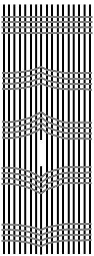
Above ignored a couple things... the force applied to the cross threads is perpendicular to them and since they are not rigid they deform. This is shown at right. The top cross weave is shown straight as in a static condition with no breakage. The lower cross weaves are shown as they might deform if an axial thread is broken. The axial threads may become closer in this region as well depending on how the weave is done.
With the angling of the cross weave the tension in them is actually the holding tension we mention above divided by the sine of the angle of their final position. If we arrange them such that each thread is holding 1% and they have an angle of 30% (just a number tossed in here for now) then we get the tension in the cross thread is 2%. A detailed analysis will be needed but it looks like the angle of deformation may actually be small and hold well. A lot depends on the specifics of the weave, specifically on how tight it is.


