ArchiveSchematics
Space Elevator Component Schematics
This page is for storing and discussing schematic designs that are perhaps too large or complex for other locations. These schematics are generally works in progress.
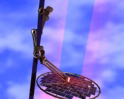
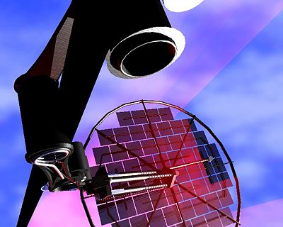
Edwards, split arm design with shock absorbers.
Edwards: This design I put together as an alternative concept to try to make a more robust system. This was originally designed as a competition climber but I believe it could be scaled up to a full scale design.
The force the rollers apply into the ribbon is partially from the spring in the middle roller but more so from weight of the climber itself. This design can be mounted to the ribbon by turning the climber at an angle and sliding it into place. A second design considered had both arms on the same side of the ribbon to make mounting easier. Motors are seen here on the upper and lower rollers though how many and which rollers is open to design constraints.
Another item here is that I attempted to shock mount the PV array to reduce its movement and any potentially damaging vibrations. I am not sure I got the entire dynamics correct but it should do vertical, horizontal and rotational damping of everything faster than about 1Hz. When I built a model of this it appeared to roughly work but I was unable to complete the construction. The issue I had was that the shocks as shown here and the way I built it bind under the off axis loads. Shocks designed to handle vertical bending loads are required - these are pretty straight forward if you think of sliding drawers.

